Selasa, 21 Januari 2014
Browse Manual »
Wiring »
bicycle
»
pico
»
turbine
»
wheel
»
wind
»
with
»
Pico Wind Turbine With Bicycle Wheel
This cheap homemade Pico-class wind turbine is made with several components of a bicycle wheel. Such as: bearings and axle along housing (hub), rim. Bicycle wheel hub has proven strong enough to bear the weight up to 100 kg, resistant to: water, dust and mud; can spin at high speed, available in the market at an affordable price. If broken it will be easily repaired. For downhill mountain bike, axles bear much larger than 100 kg load.
Because of that, those bicycle wheel components are decided to use for this turbine. Photo below shows 3 turbine blades made of aluminum, a bicycle wheel rim that serves as pulley and seen as a circle, and in the center is bicycle wheel hub. Turbine blade pitch angle can be adjusted (adjustable pitch) by simply turning the nut. This cheap wind turbine can generate 17 watts of electric power at wind speeds as low as 20 kmh.
For all photos and drawings, please click on photos and drawings for a bigger version.

More detail for the middle section can be seen in the photo below.

Turbine blade material is aluminum 1100 with 1 mm thickness and it is widely available in the market. Actually it would be more stronger if using aluminum 5083, but it is not available in small quantity.
The center of the turbine is a triangular-shaped steel plate. The triangular plate serves to hold the turbine blades on a bicycle wheel hub. There are two pieces of triangular plates with 6 of 12 mm bolts (M8 thread) to clamp the bicycle wheel hub. That 12 mm bolts are also holding turbine blades, each blade fastened by three bolts.
The photo above shows a bicycle wheel rim (circular shaped) size 16 inches, which is fastened with 3 screws M4 to the blades of the turbine and rotates with the turbine. Each blade has a 1 piece bolt that ties the rim. The rim serves as a pulley which turns a dynamo via belt transmission. A green transmission belt and dynamo pulley are shown at the bottom center of the photo.

The above drawing is a triangular plate design to tie turbine blades on a bicycle wheel hub. All units are in millimeters. Because the upload, download and print process, the scale will not match the actual parts. For red number (31) please ensure to bicycle wheel hub that you have. This plate is made of 4 mm steel. Do not use an hardened steel as it would not easy to cut and drill. Mild steel that widely available in the market at affordable prices is sufficient. There are 2 pieces of triangular plate are used for this turbine, which is positioned at the front and at the back, to clamp bicycle wheel hub and also to hold blades.
There are 6 holes of 8 mm diameter for M8 bolts. Position of each hole must be precise because it will affect turbine blades installation. As seen in the above photo turbine blades are overlapping. Note on each corner of triangle plate, each bolt in triangle corner is designed to be holding two blades at once, so efficiently. Theore with 3 bolts to hold each blade, and the total number of turbine blades are 3 blades, it does not use 9 bolts, but only use 6 bolts. If this triangle plate fabrication was not precise then turbine blades would be difficult to install.
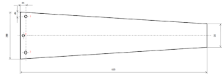
Turbine blades are made from 1 mm thick aluminum 1100. Width at the base is 200 mm, width at the tip is 55 mm, and the length of 670 mm. Note the red numbers, there are three holes of 8 mm. To drill hole 1 and hole 2, the blade must be cut from aluminum sheet. By using the above triangular steel plate as a pattern or a die, hole number 1 and 2 can be drilled. Position triangle plate so that the axis of the hole number 1 is 20 mm from the side of the blade length, and 25 mm from the base of the blade, see picture below. After hole number 1 is drilled, put bolt into hole number 1 so the blade and triangle plate are sandwiched. Align the base of the blade to become parallel with the edge of triangle plate, then hole number 2 can be drilled with guidance by triangle plate.


The photo below is a bicycle wheel hub, and it is for the front wheel.

The following photo shows the 12 mm bolt with M8 thread and thread length of 80 mm. Washers width 28 mm, 12 mm nut with collar / flange, and 12 mm regular nut. In total there are 6 long bolts, 12 washers, 24 flange nuts, and 3 regular nut, in one turbine.

After blade has a finished hole number 3, then that blade can be used as a pattern for other two blades. When three turbine blades are finished cutting and drilling, then they can be curved to form a wing profile. I usually use an electric grid pole as the base to press blade to form wing profile. The figure below shows how to press the flat plate against the electric grid pole to bend it and become a turbine blade with wing profile.

Grid pole has diameter of about 20 cm. Note that the plate axis is aligned with the electric pole axis. After wing profiles are formed, those three blades are installed as the photo below.

Shown in the photo above are three blades installation, with the turbine facing up. Bicycle wheel hub is pressed or clamped in the middle. One of triangle plate is visible at the top, the other triangle plate is under blade number 3. The far right and the far left bolts are holding two blades at once. Rightmost blade wing profile is adjusted by adjusting two nuts on the right bolt, so that there is a distance of 30 mm (yellow color). The greater the distance the greater pitch angle of wing profile, the easier turbine to start spinning. But too big pitch angle will cause high drag at high speed. Blade number 3 wing profile is adjusted by two nuts on the left bolt. Check alignment and symmetrical position of those three turbine blades, adjust by loosening and tightening nuts.
Wing profile at blade tip will appear as shown below.
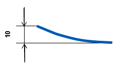
With the turbine facing up, blade tip leading and trailing edge will create a distance of 10 mm because of the pitch angle. Suppose there is a wind blowing from the top of drawing, the blade will move to the left. Pitch angle also affects the strength of the blade, in addition to affecting the speed. The greater pitch angle the stronger the blade. Conversely, the smaller pitch angle of blade, will be more easily bent backwards when blown by the wind.
With a distance of 10 mm between the leading and trailing edge, the blade can stand high wind and easily start spinning by low wind with speed of 10 kmh or 2.8 ms.

Pico Wind Turbine With Bicycle Wheel
This cheap homemade Pico-class wind turbine is made with several components of a bicycle wheel. Such as: bearings and axle along housing (hub), rim. Bicycle wheel hub has proven strong enough to bear the weight up to 100 kg, resistant to: water, dust and mud; can spin at high speed, available in the market at an affordable price. If broken it will be easily repaired. For downhill mountain bike, axles bear much larger than 100 kg load.
Because of that, those bicycle wheel components are decided to use for this turbine. Photo below shows 3 turbine blades made of aluminum, a bicycle wheel rim that serves as pulley and seen as a circle, and in the center is bicycle wheel hub. Turbine blade pitch angle can be adjusted (adjustable pitch) by simply turning the nut. This cheap wind turbine can generate 17 watts of electric power at wind speeds as low as 20 kmh.
For all photos and drawings, please click on photos and drawings for a bigger version.
Turbine blade material is aluminum 1100 with 1 mm thickness and it is widely available in the market. Actually it would be more stronger if using aluminum 5083, but it is not available in small quantity.
The center of the turbine is a triangular-shaped steel plate. The triangular plate serves to hold the turbine blades on a bicycle wheel hub. There are two pieces of triangular plates with 6 of 12 mm bolts (M8 thread) to clamp the bicycle wheel hub. That 12 mm bolts are also holding turbine blades, each blade fastened by three bolts.
The photo above shows a bicycle wheel rim (circular shaped) size 16 inches, which is fastened with 3 screws M4 to the blades of the turbine and rotates with the turbine. Each blade has a 1 piece bolt that ties the rim. The rim serves as a pulley which turns a dynamo via belt transmission. A green transmission belt and dynamo pulley are shown at the bottom center of the photo.
There are 6 holes of 8 mm diameter for M8 bolts. Position of each hole must be precise because it will affect turbine blades installation. As seen in the above photo turbine blades are overlapping. Note on each corner of triangle plate, each bolt in triangle corner is designed to be holding two blades at once, so efficiently. Theore with 3 bolts to hold each blade, and the total number of turbine blades are 3 blades, it does not use 9 bolts, but only use 6 bolts. If this triangle plate fabrication was not precise then turbine blades would be difficult to install.
Turbine blades are made from 1 mm thick aluminum 1100. Width at the base is 200 mm, width at the tip is 55 mm, and the length of 670 mm. Note the red numbers, there are three holes of 8 mm. To drill hole 1 and hole 2, the blade must be cut from aluminum sheet. By using the above triangular steel plate as a pattern or a die, hole number 1 and 2 can be drilled. Position triangle plate so that the axis of the hole number 1 is 20 mm from the side of the blade length, and 25 mm from the base of the blade, see picture below. After hole number 1 is drilled, put bolt into hole number 1 so the blade and triangle plate are sandwiched. Align the base of the blade to become parallel with the edge of triangle plate, then hole number 2 can be drilled with guidance by triangle plate.
Below drawing describes how to use triangle plate as a pattern to drill hole 1 and 2. Position of hole 1 is used as a erence point. Then align triangle edge (red) with the base of blade (yellow), so that the position of hole 2 is obtained.
Hole number 3 slightly oval shape and somewhat difficult to mark and to drill, because of its position on the curved part of blade to form a wing profile. See the picture below, the blade that has been cut (light blue) already has hole number 1 and 2. Blade mounted on two triangular plates (gray) with two long bolts. Between the two plates there is a bicycle wheel hub pinched, and serves as a spacer between those two triangle plates. Bend the blade at hole number 3 position to about 30 mm form the wing profile. As seen on the right, hole number 3 is drilled by a drill bit. Vise and drill stand are needed to drill hole number 3, the result hole will be in oval shaped. The wing profile blade can be adjusted by nuts of bolt in hole 3, so this turbine has adjustable pitch angle. Be sure to always use a wide ring and collar nut to press the blade against the triangle plate. If using an ordinary nut, the blade can be damaged as it is pressed.
Grid pole has diameter of about 20 cm. Note that the plate axis is aligned with the electric pole axis. After wing profiles are formed, those three blades are installed as the photo below.
Wing profile at blade tip will appear as shown below.
With the turbine facing up, blade tip leading and trailing edge will create a distance of 10 mm because of the pitch angle. Suppose there is a wind blowing from the top of drawing, the blade will move to the left. Pitch angle also affects the strength of the blade, in addition to affecting the speed. The greater pitch angle the stronger the blade. Conversely, the smaller pitch angle of blade, will be more easily bent backwards when blown by the wind.
With a distance of 10 mm between the leading and trailing edge, the blade can stand high wind and easily start spinning by low wind with speed of 10 kmh or 2.8 ms.
According to the test I did, the minimum distance between the leading edge to the trailing edge is 3 mm. If set to a minimum distance, turbine blade wing profile (airfoil) will be flattened thereby reducing drag while spinning at high speed. As drag reduced, then the turbine will spin faster and the power will increase. The effect of low profile blade can be seen at wind speeds above 20 kmh or 5.6 ms, the power will be increased by about 30%. But the strength of the blades will be much reduced, you should use aluminum 5083 as material for low profile blades.
In addition to nuts adjusment, blade angle can also be adjusted (pitch adjustment) by curving the blade. Make sure all the blades have the same curve or wing profile. Theore, this wind turbine has two ways to adjust pitch angle and wing profile. You can play with different pitch adjustment and wing profile to suit your conditions.
Note the use of the ring and flange nut to press and hold blades. Flange nuts are also used for clamping triangle plate to avoid that nuts loose easily. While regular nut is used only for locking flange nuts, look at the bottom of the bolt in the middle.
Prepare a bicycle wheel rim size of 16 inches. Keep in mind that 16 inches is not the diameter of wheel rim, but it is the size of a bicycle tire that can be fitted on that rim. 16 inches rim has inside diameter of about 288 mm, and become a pulley of 905 mm circumference.
Drill 3 holes of 4 mm diameter at bicycle wheel rim size 16 inches. Make sure those 3 holes are equidistant from one another. Put turbine facing down, make sure in level position like the photo below. Put the bicycle wheel rim on the turbine, use 3 paper clips to hold rim to blades. With a vernier caliper make sure rim position is really centric to the axis of turbine hub. Mark position of those 3 rim holes on blades, then drill those 3 holes on turbine blades for bolts to hold the rim. Position of 3 holes on blades must be at flat part of blade, not at curved part (wing profile) of blade.

The second from the top photo most shows rim is fastened by M4 screws with a length of about 15 mm. That photo shows also bolts are positioned on the flat area of blades, not on curved area. Screws have wide washers and also rectangular aluminum patches to reinforce screw area. Rim also glued to stick to the blades. Glue that I normally use is Aica Aibon as it is waterproof and can stand with vibration. Ive tried with epoxy type glue but it just fall out due to vibration.
Turbine needs balancing prior to use. It is balanced by mounted it vertically on the frame and rotated by hand, then allow it to stop by itself. If frame has not fabricated yet, use a vice to hold turbine axle bolt, make sure thread will not damaged by using wooden wedges. Make sure there is no wind in the balancing area, better if it is inside a closed room or garage. The most heavy blade will always stop at the bottom. Balancing is done by cutting the most heavy blade tip a little, about 1-2 mm. Then turn the turbine again by hand, and let it stop by itself. If blades stop positions are always changing or random, that means turbine blades are balanced.
In addition to nuts adjusment, blade angle can also be adjusted (pitch adjustment) by curving the blade. Make sure all the blades have the same curve or wing profile. Theore, this wind turbine has two ways to adjust pitch angle and wing profile. You can play with different pitch adjustment and wing profile to suit your conditions.
Note the use of the ring and flange nut to press and hold blades. Flange nuts are also used for clamping triangle plate to avoid that nuts loose easily. While regular nut is used only for locking flange nuts, look at the bottom of the bolt in the middle.
Prepare a bicycle wheel rim size of 16 inches. Keep in mind that 16 inches is not the diameter of wheel rim, but it is the size of a bicycle tire that can be fitted on that rim. 16 inches rim has inside diameter of about 288 mm, and become a pulley of 905 mm circumference.
Drill 3 holes of 4 mm diameter at bicycle wheel rim size 16 inches. Make sure those 3 holes are equidistant from one another. Put turbine facing down, make sure in level position like the photo below. Put the bicycle wheel rim on the turbine, use 3 paper clips to hold rim to blades. With a vernier caliper make sure rim position is really centric to the axis of turbine hub. Mark position of those 3 rim holes on blades, then drill those 3 holes on turbine blades for bolts to hold the rim. Position of 3 holes on blades must be at flat part of blade, not at curved part (wing profile) of blade.
Turbine needs balancing prior to use. It is balanced by mounted it vertically on the frame and rotated by hand, then allow it to stop by itself. If frame has not fabricated yet, use a vice to hold turbine axle bolt, make sure thread will not damaged by using wooden wedges. Make sure there is no wind in the balancing area, better if it is inside a closed room or garage. The most heavy blade will always stop at the bottom. Balancing is done by cutting the most heavy blade tip a little, about 1-2 mm. Then turn the turbine again by hand, and let it stop by itself. If blades stop positions are always changing or random, that means turbine blades are balanced.
Langganan:
Posting Komentar (Atom)
Tidak ada komentar:
Posting Komentar